Week 7 [Sep 30]
- [W7.1] Architecture
Architecture Diagrams
-
[W7.1a] Design → Introduction → What
-
[W7.1b] Design → Architecture → Architecture Diagrams → Reading
-
[W7.1c] Design → Introduction → Multi-Level Design
Architectural Styles
-
[W7.1d] Design → Architecture → Styles → What
-
[W7.1e] Design → Architecture → Styles → n-Tier Style → What
-
[W7.1f] Design → Architecture → Styles → Client-Server Style → What
-
[W7.1g] Design → Architecture → Styles → Event-Driven Style → What
-
[W7.1h] Design → Architecture → Styles → More Styles
-
[W7.1i] Design → Architecture → Styles → Using Styles
APIs
- [W7.1j] Implementation → Reuse → APIs → What
- [W7.2] Basic Design Approaches
- [W7.3] UML: Activity Diagrams
- [W7.4] Project Mgt: Scheduling and Tracking
-
[W7.4a] Project Management → Project Planning → Milestones
-
[W7.4b] Project Management → Project Planning → Buffers
-
[W7.4c] Project Management → Project Planning → Issue Trackers
-
[W7.4d] Project Management → Project Planning → Work Breakdown Structure
-
[W7.4e] Project Management → Project Planning → GANTT Charts
-
[W7.4f] Project Management → Project Planning → PERT Charts
-
[W7.4g] Project Management → Teamwork → Team Structures
- [W7.5] Advanced Java
Architecture Diagrams
W7.1a Design → Introduction → What
Can explain what is software design
Design in the creative process of transforming the problem into a solution; the solution is also called design. -- 📖 Software Engineering Theory and Practice, Shari Lawrence; Atlee, Joanne M. Pfleeger
Software design has two main aspects:
- Product/external design: designing the external behavior of the product to meet the users' requirements. This is usually done by product designers with the input from business analysts, user experience experts, user representatives, etc.
- Implementation/internal design: designing how the product will be implemented to meet the required external behavior. This is usually done by software architects and software engineers.
W7.1b Design → Architecture → Architecture Diagrams → Reading
Can interpret an architecture diagram
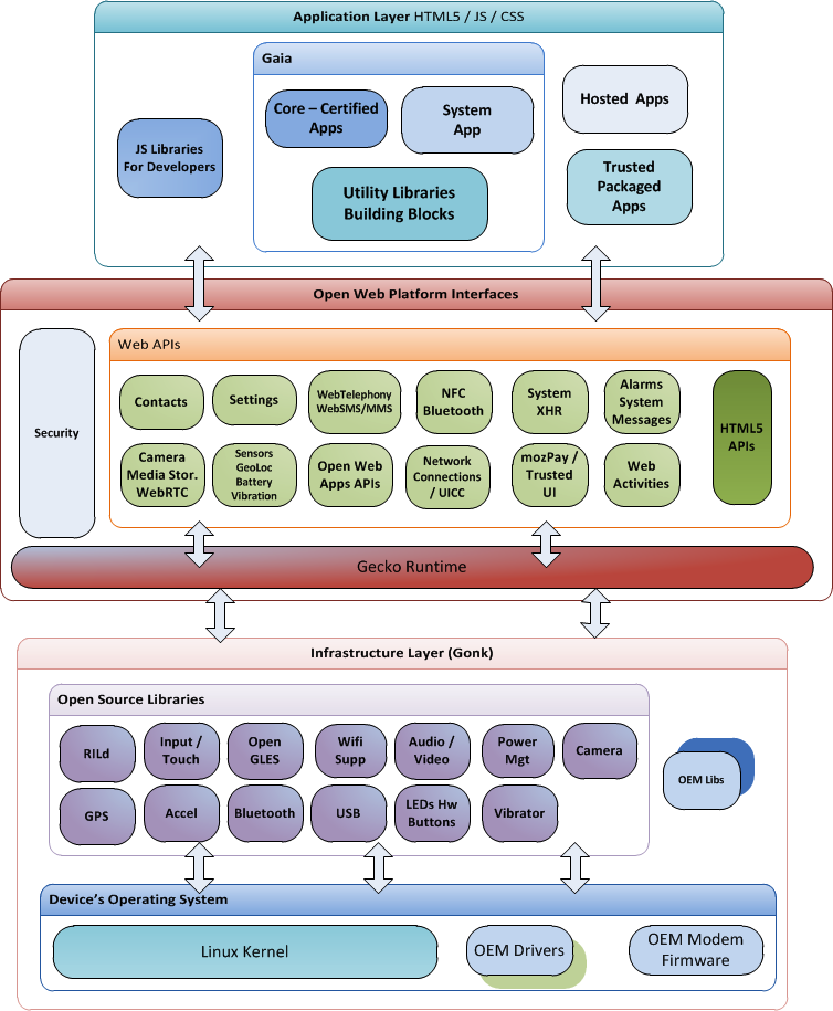
Architecture diagrams are free-form diagrams. There is no universally adopted standard notation for architecture diagrams. Any symbol that reasonably describes the architecture may be used.
Some example architecture diagrams:

W7.1c Design → Introduction → Multi-Level Design
Can explain multi-level design
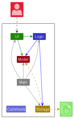
In a smaller system, design of the entire system can be shown in one place.
This class diagram of se-edu/addressbook-level2 depicts the design of the entire software.
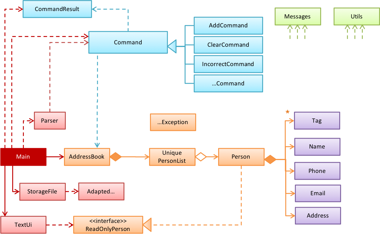
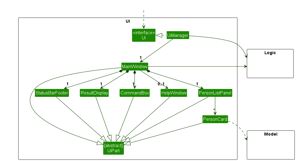
Design of bigger systems needs to be done/shown at multiple levels.
This architecture diagram of se-edu/addressbook-level3 depicts the high-level design of the software.

Here are examples of lower level designs of some components of the same software:
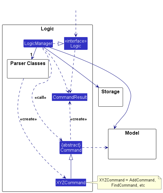
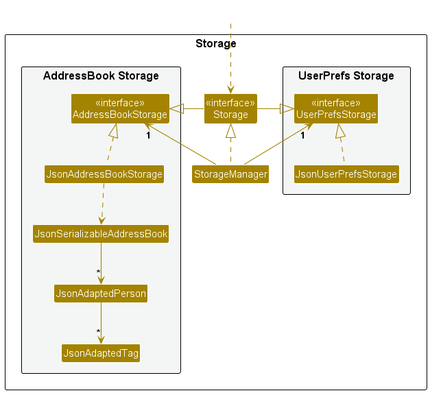
Architectural Styles
W7.1d Design → Architecture → Styles → What
Can explain architectural styles
Software architectures follow various high-level styles (aka architectural patterns), just like
n-tier style, client-server style, event-driven style, transaction processing style, service-oriented style, pipes-and-filters style, message-driven style, broker style, ...
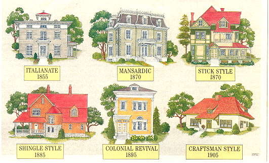
source: https://inspectapedia.com
W7.1e Design → Architecture → Styles → n-Tier Style → What
Can identify n-tier architectural style
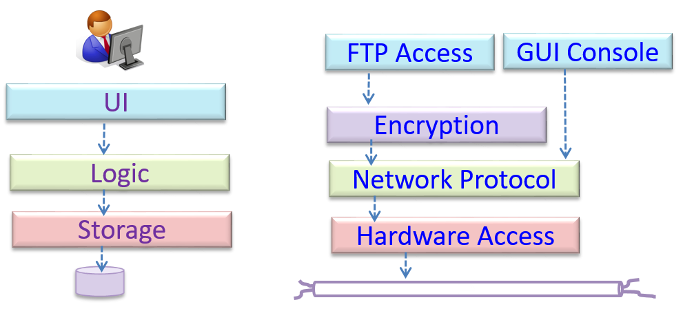
In the n-tier style, higher layers make use of services provided by lower layers. Lower layers are independent of higher layers. Other names: multi-layered, layered.
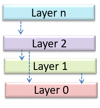
Operating systems and network communication software often use n-tier style.
W7.1f Design → Architecture → Styles → Client-Server Style → What
Can identify the client-server architectural style
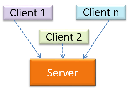
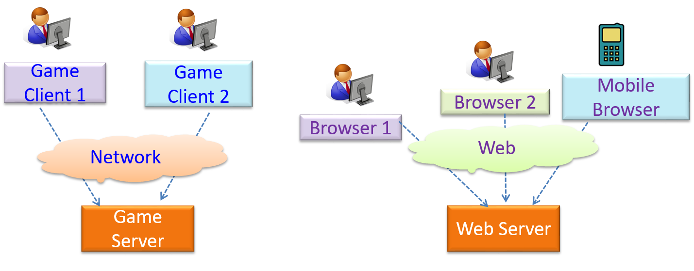
The client-server style has at least one component playing the role of a server and at least one client component accessing the services of the server. This is an architectural style used often in distributed applications.
The online game and the Web application below uses the client-server style.
W7.1g Design → Architecture → Styles → Event-Driven Style → What
Can identify event-driven architectural style
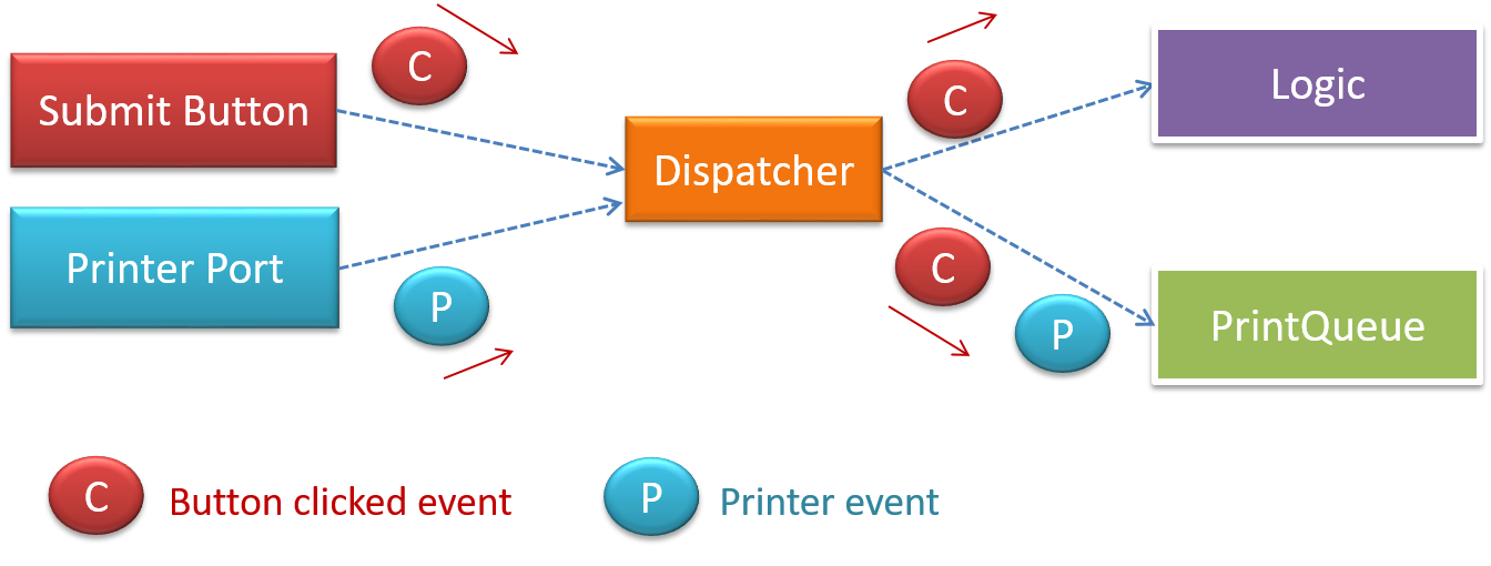
Event-driven style controls the flow of the application by detecting

When the ‘button clicked’ event occurs in a GUI, that event can be transmitted to components that are interested in reacting to that event. Similarly, events detected at a Printer port can be transmitted to components related to operating the Printer. The same event can be sent to multiple consumers too.
W7.1h Design → Architecture → Styles → More Styles
Can name several other architecture styles
Other well-known architectural styles include the pipes-and-filters architectures, the broker architectures, the peer-to-peer architectures, and the message-oriented architectures.
-
Pipes and Filters pattern -- an article from Microsoft about the pipes and filters architectural style
-
Broker pattern -- Wikipedia article on the broker architectural style
-
Peer-to-peer pattern -- Wikipedia article on the P2P architectural style
-
Message-driven processing -- a post by Margaret Rouse
W7.1i Design → Architecture → Styles → Using Styles
Can explain how architectural styles are combined
Most applications use a mix of these architectural styles.
An application can use a client-server architecture where the server component comprises several layers, i.e. it uses the n-Tier architecture.
Assume you are designing a multiplayer version of the Minesweeper game where any number of players can play the same Minefield. Players use their own PCs to play the game. A player scores by deducing a cell correctly before any of the other players do. Once a cell is correctly deduced, it appears as either marked or cleared for all players.
Comment on how each of the following architectural styles could be potentially useful when designing the architecture for this game.
- Client-server
- Transaction-processing
- SOA (Service Oriented Architecture)
- multi-layer (n-tier)
- Client-server – Clients can be the game UI running on player PCs. The server can be the game logic running on one machine.
- Transaction-processing – Each player action can be packaged as transactions (by the client component running on the player PC) and sent to the server. Server processes them in the order they are received.
- SOA – The game can access a remote web services for things such as getting new puzzles, validating puzzles, charging players subscription fees, etc.
- Multi-layer – The server component can have two layers: logic layer and the storage layer.

APIs
W7.1j Implementation → Reuse → APIs → What
Can explain APIs
An Application Programming Interface (API) specifies the interface through which other programs can interact with a software component. It is a contract between the component and its clients.
A class has an API (e.g., API of the Java String class, API of the Python str class) which is a collection of public methods that you can invoke to make use of the class.
The GitHub API is a collection of Web request formats GitHub server accepts and the corresponding responses. We can write a program that interacts with GitHub through that API.
When developing large systems, if you define the API of each components early, the development team can develop the components in parallel because the future behavior of the other components are now more predictable.
Choose the correct statements
- a. A software component can have an API.
- b. Any method of a class is part of its API.
- c. Private methods of a class are not part of its API.
- d. The API forms the contract between the component developer and the component user.
- e. Sequence diagrams can be used to show how components interact with each other via APIs.
(a) (c) (d) (e)
Explanation: (b) is incorrect because private methods cannot be a part of the API
Defining component APIs early is useful for developing components in parallel.
True
Explanation: Yes, once we know the precise behavior expected of each component, we can start developing them in parallel.
W7.2a Design → Design Approaches → Top-Down and Bottom-Up Design
Can explain top-down and bottom-up design
Multi-level design can be done in a top-down manner, bottom-up manner, or as a mix.
- Top-down: Design the high-level design first and flesh out the lower levels later. This is especially useful when designing big and novel systems where the high-level design needs to be stable before lower levels can be designed.
- Bottom-up: Design lower level components first and put them together to create the higher-level systems later. This is not usually scalable for bigger systems. One instance where this approach might work is when designing a variations of an existing system or re-purposing existing components to build a new system.
- Mix: Design the top levels using the top-down approach but switch to a bottom-up approach when designing the bottom levels.
Top-down design is better than bottom-up design.
False
Explanation: Not necessarily. It depends on the situation. Bottom-up design may be preferable when there are lot of existing components we want to reuse.
W7.2b Design Approaches → Agile Design → Agile Design
Can explain agile design
Agile design can be contrasted with full upfront design in the following way:
Agile designs are emergent, they’re not defined up front. Your overall system design will emerge over time, evolving to fulfill new requirements and take advantage of new technologies as appropriate. Although you will often do some initial architectural modeling at the very beginning of a project, this will be just enough to get your team going. This approach does not produce a fully documented set of models in place before you may begin coding. -- adapted from agilemodeling.com
Agile design camp expects the design to change over the product’s lifetime.
True
Explanation: Yes, that is why they do not believe in spending too much time creating a detailed and full design at the very beginning. However, the architecture is expected to remain relatively stable even in the agile design approach.
W7.3a Design → Modelling → Modelling Behaviors Activity Diagrams - Basic
Can use basic-level activity diagrams
Software projects often involve workflows. Workflows define the
Some examples in which a certain workflow is relevant to software project:
A software that automates the work of an insurance company needs to take into account the workflow of processing an insurance claim.
The algorithm of a price of code represents the workflow (i.e. the execution flow) of the code.
Which of these sequence of actions is not allowed by the given activity diagram?
- i. start a b c d end
- ii. start a b c d e f g c d end
- iii. start a b c d e g f c d end
- iv. start a b c d g c d end

(iv)
Explanation: -e-f- and -g- are parallel paths. Both paths should complete before the execution reaches c again.
Draw an activity diagram to represent the following workflow a burger shop uses when processing an order by a customer.
- First, a cashier takes the order.
- Then, three workers start preparing the order at the same time; one prepares the drinks, one prepares the burgers, and one prepares the desserts.
- In the meantime, the customer pays for the order. If the customer has a voucher, she pays using the voucher; otherwise she pays using cash.
- After paying, the customer collects the food after all three parts of the order are ready.
W7.3b Design → Modelling → Modelling Behaviors Activity Diagrams - Intermediate
Can use intermediate-level activity diagrams
W7.4a Project Management → Project Planning → Milestones
Can explain milestones
A milestone is the end of a stage which indicates a significant progress. We should take into account dependencies and priorities when deciding on the features to be delivered at a certain milestone.
Each intermediate product release is a milestone.
In some projects, it is not practical to have a very detailed plan for the whole project due to the uncertainty and unavailability of required information. In such cases, we can use a high-level plan for the whole project and a detailed plan for the next few milestones.
Milestones for the Minesweeper project, iteration 1
| Day | Milestones |
|---|---|
| Day 1 | Architecture skeleton completed |
| Day 3 | ‘new game’ feature implemented |
| Day 4 | ‘new game’ feature tested |
W7.4b Project Management → Project Planning → Buffers
Can explain buffers
A buffer is a time set aside to absorb any unforeseen delays. It is very important to include buffers in a software project schedule because effort/time estimations for software development is notoriously hard. However, do not inflate task estimates to create hidden buffers; have explicit buffers instead. Reason: With explicit buffers it is easier to detect incorrect effort estimates which can serve as a feedback to improve future effort estimates.

W7.4c Project Management → Project Planning → Issue Trackers
Can explain issue trackers
Keeping track of project tasks (who is doing what, which tasks are ongoing, which tasks are done etc.) is an essential part of project management. In small projects it may be possible to track tasks using simple tools as online spreadsheets or general-purpose/light-weight tasks tracking tools such as Trello. Bigger projects need more sophisticated task tracking tools.
Issue trackers (sometimes called bug trackers) are commonly used to track task assignment and progress. Most online project management software such as GitHub, SourceForge, and BitBucket come with an integrated issue tracker.
A screenshot from the Jira Issue tracker software (Jira is part of the BitBucket project management tool suite):
W7.4d Project Management → Project Planning → Work Breakdown Structure
Can explain work breakdown structures
A Work Breakdown Structure (WBS) depicts information about tasks and their details in terms of subtasks. When managing projects it is useful to divide the total work into smaller, well-defined units. Relatively complex tasks can be further split into subtasks. In complex projects a WBS can also include prerequisite tasks and effort estimates for each task.
The high level tasks for a single iteration of a small project could look like the following:
| Task ID | Task | Estimated Effort | Prerequisite Task |
|---|---|---|---|
| A | Analysis | 1 man day | - |
| B | Design | 2 man day | A |
| C | Implementation | 4.5 man day | B |
| D | Testing | 1 man day | C |
| E | Planning for next version | 1 man day | D |
The effort is traditionally measured in man hour/day/month i.e. work that can be done by one person in one hour/day/month. The Task ID is a label for easy reference to a task. Simple labeling is suitable for a small project, while a more informative labeling system can be adopted for bigger projects.
An example WBS for a project for developing a game.
| Task ID | Task | Estimated Effort | Prerequisite Task |
|---|---|---|---|
| A | High level design | 1 man day | - |
| B |
Detail design
|
2 man day
|
A |
| C |
Implementation
|
4.5 man day
|
|
| D | System Testing | 1 man day | C |
| E | Planning for next version | 1 man day | D |
All tasks should be well-defined. In particular, it should be clear as to when the task will be considered done.
Some examples of ill-defined tasks and their better-defined counterparts:
| Bad | Better |
|---|---|
| more coding | implement component X |
| do research on UI testing | find a suitable tool for testing the UI |
Which one these project tasks is not well-defined?
(c)
Explanation: ‘More testing’ is not well-defined. How much is ‘more’? ‘Test the delete functionality’ is a better-defined task.
W7.4e Project Management → Project Planning → GANTT Charts
Can explain GANTT charts
A Gantt chart is a 2-D bar-chart, drawn as time vs tasks (represented by horizontal bars).
A sample Gantt chart:

In a Gantt chart, a solid bar represents the main task, which is generally composed of a number of subtasks, shown as grey bars. The diamond shape indicates an important deadline/deliverable/milestone.
W7.4f Project Management → Project Planning → PERT Charts
Can explain PERT charts
PERT (Program Evaluation Review Technique) chart uses a graphical technique to show the order/sequence of tasks. It is based on a simple idea of drawing a directed graph in which:
- Node or vertex captures the effort estimation of a task, and
- Arrow depicts the precedence between tasks
an example PERT chart for a simple software project

md = man days
A PERT chart can help determine the following important information:
- The order of tasks. In the example above,
Final Testingcannot begin until all coding of individual subsystems have been completed. - Which tasks can be done concurrently. In the example above, the various subsystem designs can start independently once the
High level designis completed. - The shortest possible completion time. In the example above, there is a path (indicated by the shaded boxes) from start to end that determines the shortest possible completion time.
- The Critical Path. In the example above, the shortest possible path is also the critical path.
Critical path is the path in which any delay can directly affect the project duration. It is important to ensure tasks on the critical path are completed on time.
W7.4g Project Management → Teamwork → Team Structures
Can explain common team structures
Given below are three commonly used team structures in software development. Irrespective of the team structure, it is a good practice to assign roles and responsibilities to different team members so that someone is clearly in charge of each aspect of the project. In comparison, the ‘everybody is responsible for everything’ approach can result in more chaos and hence slower progress.

Egoless team
In this structure, every team member is equal in terms of responsibility and accountability. When any decision is required, consensus must be reached. This team structure is also known as a democratic team structure. This team structure usually finds a good solution to a relatively hard problem as all team members contribute ideas.
However, the democratic nature of the team structure bears a higher risk of falling apart due to the absence of an authority figure to manage the team and resolve conflicts.
Chief programmer team
Frederick Brooks proposed that software engineers learn from the medical surgical team in an operating room. In such a team, there is always a chief surgeon, assisted by experts in other areas. Similarly, in a chief programmer team structure, there is a single authoritative figure, the chief programmer. Major decisions, e.g. system architecture, are made solely by him/her and obeyed by all other team members. The chief programmer directs and coordinates the effort of other team members. When necessary, the chief will be assisted by domain specialists e.g. business specialists, database expert, network technology expert, etc. This allows individual group members to concentrate solely on the areas where they have sound knowledge and expertise.
The success of such a team structure relies heavily on the chief programmer. Not only must he be a superb technical hand, he also needs good managerial skills. Under a suitably qualified leader, such a team structure is known to produce successful work. .
Strict hierarchy team
In the opposite extreme of an egoless team, a strict hierarchy team has a strictly defined organization among the team members, reminiscent of the military or bureaucratic government. Each team member only works on his assigned tasks and reports to a single “boss”.
In a large, resource-intensive, complex project, this could be a good team structure to reduce communication overhead.
Which team structure is the most suitable for a school project?
(a)
Explanation: Given that students are all peers and beginners, Egoless team structure seems most suitable for a school project. However, given school projects are low-stakes, short-lived, and small, even the other two team structures can be used for them.
Streams
W7.5a Tools → Java → Streams: Basic
Can use Java8 streams
Java 8 introduced a number of new features (e.g. Lambdas, Streams) that are not trivial to learn but also extremely useful to know.
Here is an overview of new Java 8 features .(written by Benjamin Winterberg)
Tutorials:
-
Java 8 Tutorial -- from tutorialspoint.com. Also provides a way to try out code online
A video tutorial by well-known Java coach Venkat Subramaniam
Java: JavaFX
W7.5b Tools → Java → JavaFX
Can use JavaFX to build a simple GUI
JavaFX is a technology for building Java-based GUIs. Previously it was a part Java itself, but has become a third-party dependency since then. It is now being maintained by OpenJDK.

